|
||||||
AN EXTERNAL-AMPLIFIER CONTROL CIRCUIT FOR THE IC-706 MK 2.
80 September 1999 QST
After buying a new IC-706 MK2, my enthusiasm was overflowing on the way home from the store. I was going to hook up my little (27 pounds) 450-W amplifier and have some fun. To my disappointment, there was no jack on the new rig to control an outboard amplifier. Consulting the manual did not help because I was not about to buy an IC-4KL with a remote control. However,
after studying the ACC socket connection, a solution came to light. At pin 3, the orange wire goes from +8 V when receiving to ground or negative when transmitting. Fig 3 is a two-transistor circuit to close a reed relay when transmitting. This circuit is the brainchild of W3NNL. In a few hours, I built it on a RadioShack #276-148 dual mini-circuit board. (Fritz snapped the board
in half to make two smaller boards.-Ed.) I used one half of the board to terminate the 13 wires from the ACC socket. The board is clamped to the cable jacket. The other half of the board contains the two-transistor circuit plus two phono jacks to make the relay and ALC connections. Pin 8 (gray wire) supplies +12 V for the circuit, pin 2 (red wire) is ground and pin 3 (orange wire) is the keying input from the ICOM. The reed relay is mounted on a very small piece of
project board (RadioShack #276-149) that is taped to the ACC cable. See Figure 4. The reed relay completely isolates the amplifier keying line from the transceiver. Since my amplifier does not have the luxury of full QSK, I use semi-QSK and a 0.2 second delay. It works great!
Figure 3-A schematic of W3NZ's circuit that lets the IC-706 Mk 2 transceiver control an external power
amplifier. All resistors are 1/4 W, 5% units. Equivalent parts may be substituted for those
shown. RS and RSU numbers are RadioShack catalog numbers. Q1, Q2-MPS2222 NPN
transistor, K1-12-V reed relay.
|
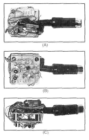
Figure 4-Photos of W3NZ's IC-706 Mk2 external amplifier-keying circuit. (A) The ACC plug and termination board. The relay is taped to the cable jacket (B) The board containing the transistor circuit and two phono jacks. One keys the amplifier; the other is for ALC. (C) A side view of the
assembly containing both boards.
Fritz Hauff, W3NZ, 875 NW 48
St, Lot 352, Pompano Beach, FL 33064
Устройство предназначено для подключения внешнего усилителя мощности к трансиверу IC-706MK2, поскольку в трансивере нет отдельного выхода для усилителя, а имеющийся слишком слаб для коммутации внешнего реле. Сигнал для коммутации и питание берутся из аксессуарного разъема АСС. Транзисторы любые средней мощности, например КТ601, КТ603 и т.д.
Прислал
И.А. Доброхотов (UN7GM),
Республика Казахстан, 480000, г.Алматы,
Главпочтамт, а/я 178. un7gm@qsl.net
| Глас народа |
|
11.03.2013 20:44 А кто нибудь собирал эту схему на отечественных компанентах .Подс... -- Alex UB9SBR... 23.12.2008 14:14 Схема хорошая,простая,буду делать.... -- Alex, RX3ZW... 23.12.2008 14:13 Схема хорошая,простая,буду делать.... -- Alex, RX3ZW... 23.12.2008 14:01 Схема хорошая,простая,буду делать.... -- Alex, RX3ZW... 19.05.2008 17:51 А для IC-703 подойдет ?... -- US1GAO 30.03.2007 18:50 Как я понял данная схема коммутации РА ориентирована на HF диапаз... -- UA9FY 24.03.2007 13:41 Существует трудность в приобретении раземов на ACC. Как выход со... -- UT0EZ 24.03.2007 13:38 Собрал.,доволен . Проблем нет!... -- UT0EZ 25.08.2005 14:01 Работает отлично с аппаратами IC-706,IC-746,IC-718 !... -- DSW |
![]()