|
||||||
VolksRTTY—An Improved HamComm Interface .
Connected to your PC and HF transceiver, this easily constructed interface puts you on RTTY and AMTOR for less than $40!
By Terry Mayhan, K7SZL
Photo by the author.
 Like many amateurs, I have long been fascinated by the digital modes but, until recently, never got around to adding this capability to my station. That changed when, last year, one of my coworkers casually handed me a computer disk with the explanation that he had found a "way cool" RTTY program on the Internet and thought that I’d be interested in it. Having seen lots of genuinely bad shareware and freeware over the years, I was initially skeptical, but graciously thanked him and agreed to take the program home and try it.
After I scanned the documentation and played with the program, my skepticism grew. The software, HamComm Version 3.1, purported to send and receive CW, RTTY and AMTOR with no more of a hardware interface than a 741 op amp and a few resistors, capacitors and diodes. Still, HamComm has a superbly intuitive user interface and a number of terrific features such as a "spectral analyzer" display that allows fast, precise receiver tuning and macros that eliminate much of the drudgery of typing call sign and contest exchanges. Intrigued by HamComm’s potential, I breadboarded the interface shown in the accompanying documentation and was pleasantly surprised to find that it worked immediately upon power-up!
A few minutes of tuning around the RTTY portion of 20 meters established that, under good conditions (medium to strong signals and minimal QRM and QRN), HamComm did a credible job of printing RTTY signals with the rudimentary interface. Receiver tuning was a snap—much easier and more accurate than what I had experienced with the tuning indicators on commercial TNCs. Finding a strong station calling CQ, I responded with a snappy 1x2 call and was rewarded with my first RTTY QSO in 35+ years of hamming! I was hooked!
After a few hours of operating with my new RTTY gear, however, it became apparent that even moderate amounts of QRM or QRN caused the "print quality" (readability) to deteriorate. Reasoning that the performance limitation lay more in the interface hardware than in the software, I set about developing an improved interface. The result of that endeavor is an easily constructed circuit that, in conjunction with HamComm, operates with any IBM-compatible PC—even vintage machines such as the XT or ’286. Power for the modem is derived from the PC’s serial (RS-232) port, so portable operation with a laptop is easily accomplished. Although performance falls a bit shy of a state-of-the-art DSP-based TNC, it is entirely suitable for serious DX, ragchewing and contest work. Given HamComm’s German heritage, the interface’s simplicity, and its excellent cost/performance ratio, I have christened it VolksRTTY—an RTTY modem for everyone. [1]
Circuit Description
See Figures 1 and 2. VolksRTTY is comprised of four functional elements: power supply, received-signal conditioner, FSK generator and TR switch. Let’s trace the signal flow through each stage before proceeding with the construction
details.
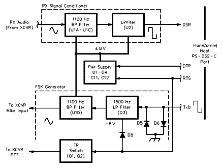
Figure 1—Simplified block diagram of the VolksRTTY
interface.
Figure 2—Schematic of the VolksRTTY modem.
Unless otherwise specified, resistors are 1/4 W, 5% tolerance carbon-composition or film units. Part numbers in parentheses are Jameco; equivalent parts can be substituted. Jameco Electronic Components, 1355 Shoreway Rd, Belmont, CA 94002; tel 800-831-4242, 650-592-8097; domestic fax 800-237-6948, 650-592-2503; international fax 650-592-2503; e-mail info@jameco.com; http://www.jameco.com
C1, C4, C7, C10, C17, C20—0.1 mF, 50 V (135562)
C2, C3, C5, C6, C8, C9, C14, C15, C18, C19—0.01 mF, 50 V (26884)
C11,C12,C16—100 mF, 16 V (94289)
C13—1 mF, 16 V (94160)
D1-D8, 1N4148 (36038) (ëþáûå ìàëîìîùíûå êðåìíèåâûå äèîäû, íàïðèìåð ÊÄ503 è ò.ä.Ïðèì.UN7GM)
J1—5-pin PC-mount DIN connector (29399)
J2—9-pin PC-mount female connector (104951, DE9S318)
P1—5-pin DIN plug; mates with J1 (15878)
Q1-Q3—2N3904 or 2N2222A (38359) (ïîäîéäóò ìàëîìîùí. npn òðàíçèñòîðû, íàïðèìåð ÊÒ342.Ïðèì.UN7GM)
U1—LM324 (23683) (àíàëîã Ê1402ÓÄ2À.Ïðèì.UN7GM)
U2—LM741 (24539) (àíàëîã Ê140ÓÄ708.Ïðèì.UN7GM)
Misc: IC sockets, hardware, 6-foot-long, 9-conductor cable with DE09 male/DE09 female connectors, mates with J2 (25700, monitor extension cable); 4.9 x 2.5 x 1.5-inch (LWD) plastic enclosure (18913); see text.
Power Supply
Depending on their logical state, the active pins of the serial port assume a nominal -10 V or +10 V level. Most IBM-compatible PCs can source about 5 mA from each of these pins before the voltage starts to sag. VolksRTTY derives its plus and minus operating voltages from the DTR and RTS pins using diodes D1 through D4 with smoothing provided by C11 and C12. During receive, DTR outputs +10 V and RTS -10 V. During transmit, DTR outputs an asymmetrical square wave corresponding to the mark/space state, while RTS goes high to turn on the TR switch. To provide operating voltages in either mode, the four diodes are cross-connected as a bridge rectifier. This simple configuration provides plus and minus rail voltages of 7 to 10 V under load, a range that is compatible with standard RS-232 levels.
RX Signal Conditioner
During receive, the station transceiver is tuned to an RTTY signal so that the mark and space audio tones (assuming 170 Hz shift) presented to the interface are nominally 1015 Hz and 1185 Hz, respectively. These tones are passed through an 1100 Hz active band-pass filter comprised of three sections of an LM324, U1. The center frequencies and Qs of each stage are staggered to provide a filter response that is flat within 3 dB over a 275 Hz bandwidth. [2] Filtered mark and space tones are applied to limiter U2, which converts the tones to square waves of the same frequency. These are applied to the serial port’s DSR pin for processing by HamComm. Software FSK detection is accomplished by measuring the period between low and high transitions. Because frequency is inversely related to period, it is a simple matter (conceptually, at least) for the software to determine whether a mark or space tone is being received.
Sharp-eyed readers may note an apparent inconsistency here: The circuit takes an analog input, performs some filtering and signal conditioning, and applies it to a serial port pin as a digital output. Where did the A/D conversion occur? In U2. A 741 op amp running open-loop for maximum gain, U2 effectively acts as a 1-bit A/D converter. Depending on the state of the limiter, its output will closely approach one of the 741’s positive or negative rail voltages. Because these voltages are compatible with RS-232-C levels, the output of the limiter is also compatible.
TR Switch
During transmit, HamComm causes the RTS line to go positive. This voltage turns on Darlington pair Q1/Q2 to pull the transceiver’s PTT line low. That switches the transceiver from receive to transmit. Operating voltage for low-pass filter Q3 is derived from the RTS line as well.
FSK Generator
HamComm tells the hardware to output a square wave on the TxD line at a frequency equal to the desired AFSK tone: either 1015 or 1185 Hz, depending on whether a mark or space is being transmitted. This square wave is clipped by D5 and D6, then applied to low-pass filter Q3 and band-pass filter U1D. The two filters attenuate the odd-order harmonics and ensure that a reasonably clean sinusoidal waveform is applied to the transceiver’s microphone input.
HamComm’s choice of mark and space frequencies is a compromise. Initially, I used a center frequency of 700 Hz reasoning that the lower frequency would make it easier to achieve the desired receive-filter band-pass characteristics. During tests, it became apparent that the FSK generator did not provide sufficient attenuation of the third harmonic of the square wave input. This harmonic manifested itself as a spurious FSK signal during transmit which, although barely discernible, had the potential to interfere with other QSOs. After considerable experimentation directed toward improving the harmonic attenuation, I finally threw in the towel and moved the center frequency to 1100 Hz. This puts the weak third harmonic pair at 3045/3355 Hz, which is sufficiently outside the band-pass of a modern SSB transceiver’s filter to ensure a clean signal.
Construction
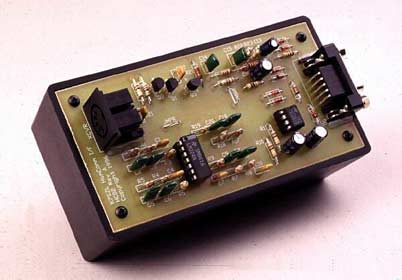
VolksRTTY can be built on a PC board, perf board with point-to-point wiring, or even "dead-bug" style (see Note [1]). Neither lead length nor component layout seems to be particularly critical. My interface was initially installed in a plastic box, as shown in the photograph. With a transmitted power output of 400 W on 40 and 20 meters, I had no problems with RF feedback. Later, after changing antennas, I did encounter some difficulty when operating on the higher bands. Since then, I’ve packaged the interface in an aluminum enclosure, and the RF problems have disappeared.
Pay close attention to the values and tolerances of the resistors and capacitors associated with U1A through U1D: Use the values specified, ideally with 5% or better tolerances. With the exception of the 0.1-mF coupling capacitors, these components establish the passband characteristics of the 1100 Hz band-pass filters.
The 0.01 mF capacitors called for in the parts list are specified by the distributor as 10% tolerance components. My experience with several hundred of these capacitors is that nine out of ten are within 3% of their nominal value. If you have a means of accurately measuring their values, install those with the greatest capacitance in stage U1A and those with the lowest capacitance in stage U1B. Use the ones closest to nominal in stages U1C and U1D. This approach broadens the filter response curve a bit and makes it flatter. If the capacitors are randomly selected, there is a tendency for the tolerance build-up to cause the filter bandwidth to be somewhat less than the design target of 275 Hz. If you aren’t able to measure the capacitor values, don’t be concerned—the impact on operational performance is quite modest, providing you use capacitors that are within a few percent of the specified value.
Avoid the temptation to replace the specified op amps with hotter devices—at least until you get the circuit working with those called for in the parts list. This is because many devices with greater gain-bandwidth products also have healthier appetites for power supply current. The excessive current draw causes VolksRTTY’s rail voltages to sag, and the circuit ceases to operate.
Installation and Checkout
First, acquire the software, HamComm V3.1 (see Notes [1] and [2]). Copy it to an appropriately named subdirectory on your computer’s hard drive (eg, C:\HC), and execute it by typing HAMCOM31. The program extracts a number of files and places them in the same subdirectory. These include the executable file (HC.EXE), a configuration file (HC31.CFG) that defines HamComm’s operating parameters and an extensive documentation file (HC.DOC). Use your favorite text editor to open HC31.CFG and, at a minimum, make the following changes:
• Line 101—Change COM2 to COM1 (or the COM port that you intend to use).
• Line 214—Set afcenter to 1100.
There are a host of other parameters that may optionally be set at the same time. These include clock timing, AMTOR timing, FSK polarity, literals containing your call, QTH, standard text phrases and many others. The configuration file is largely self-documented; careful reading will, in most cases, be sufficient to figure out what a given parameter does and how it can be modified. When you have completed these changes, save the file (don’t change the file name—it should be HC31.CFG) and exit.
Connect the VolksRTTY interface to your computer’s serial port using an appropriate serial cable and, operating in the native DOS mode (the registered version of HamComm can be run as a DOS task under Windows 95; see Notes [1] and [2]), execute HamComm by typing HC from the subdirectory containing the HamComm files. Measure the voltage at pins 4 and 7 of U2 with respect to ground. You should see +7 to +10 V on pin 7, and -7 to -10 V on pin 4. If these voltages are present, you can be reasonably sure that you have selected the correct COM port.
Complete connecting the interface to the transceiver’s receive audio, microphone and PTT lines. Receiver audio can be obtained via a parallel connection to the speaker lines, or a plug partially inserted into the headphone jack. Either approach allows you to listen to pitch cues while you are tuning in FSK signals. The best choice for microphone audio, PTT and ground connections is at the transceiver’s front-panel microphone connector. Newer transceivers have RTTY ports, but in many cases they may not be compatible with the VolksRTTY interface without modification. For now, stick with the proven approach.
Set your transceiver to the USB mode, turn off any audio filters your transceiver may have and tune to a clear spot in the band. [3] Press F7 on your keyboard, and HamComm will bring up the "spectrum analyzer" tuning indicator. With the receiver’s audio gain set at a normal listening level, you should see a display similar to that shown in Figure 3. If you want, the display can be expanded by pressing PG UP several times and then recentering the display with the arrow
keys.
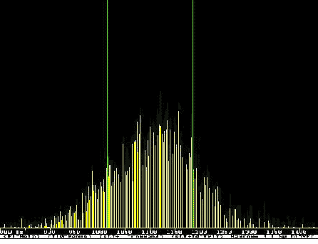
Figure 3—HamComm’s "spectrum analyzer" tuning indicator with no signal present.
The two vertical lines in Figure 3 correspond to the frequencies at which Ham-Comm expects the mark and space tones to occur. The shape of the noise spectra corresponds roughly to the filter response in the VolksRTTY interface. If your noise spectra looks like that of Figure 3, the band-pass filter is working as intended. If the spectra looks significantly different, check the wiring and components associated with U1A, U1B and U1C.
Once you have confirmed that the filter is functioning properly, set your transceiver to USB with an IF filter bandwidth of 2.7 kHz or so and tune around until you locate a strong RTTY signal. Adjust your transceiver’s main tuning until you see a spectrum analyzer display similar to the one shown in Figure 4.
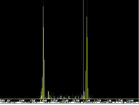
Figure 4—HamComm display of a properly tuned RTTY signal.
Your objective is to line-up the mark/space spectral lines of the RTTY signal with the vertical tuning lines. Once that is accomplished, press F3 to return to the TX/RX window in baudot RTTY mode and observe the characters being printed out. You should see signs of intelligence. In the presence of severe QRM, QRN and/or QSB, some of the characters may be corrupted. This can be minimized by selecting a narrower IF filter, if your transceiver is equipped with one. Because the bandwidth of a 45 baud RTTY signal is about 250 Hz, you don’t want to use a filter that is narrower than that. Unlike SSB voice—which requires different sideband settings depending upon the band selected—with RTTY you can always use the same sideband and RTTY polarity. If you don’t see recognizable text, confirm that HamComm is set to RTTY, 45 Baud, 170 Hz shift, and the appropriate polarity for your choice of sidebands. This is done by selecting the appropriate pull-down menus from the top of the screen using your mouse or by simultaneously pressing the ALT key and the first letter of the menu name.
After you have the receive mode functioning properly, check the transmit mode. Pick a clear frequency, turn the microphone gain to minimum (CCW), and press CTRL-T. You may hear the transceiver’s TR relay pull in and an RTTY "diddle" sound from the PC speaker. Slowly advance the transceiver’s mike gain until the plate (or collector) current is at approximately one-half the normal CW value. Because RTTY requires a 100% duty cycle, it’s not a good idea to run more power than this unless your transceiver’s operating manual provides direction to the contrary. Type a string of RYs and your call sign followed by a space. Observe that the plate (collector) current bounces around a bit. To stop transmitting, press CTRL-T or CTRL-BACKSPACE. The former switches you to receive mode immediately, while the latter switches only after HamComm’s transmit buffer is emptied. Once everything checks out, you’re ready to start looking for your first RTTY QSO!
Operating
An RTTY QSO is very similar to one on CW. With your RIT off, tune around until you find an RTTY station calling CQ. Even before the operator signs, you can start composing your call to the other station, eg, W7QC W7QC DE K7SZL K7SZL K CTRL-BACK SPACE. When the other station signs, press CTRL-T. Your transceiver will switch to transmit and the text you entered into the transmit buffer will be sent. When the buffer is empty, HamComm automatically switches your transceiver to receive. If you’ve gotten this far, you understand enough of the basics to successfully complete the QSO. You’re on your way!
AMTOR is another digital mode that is supported by HamComm. Sadly, the number of stations using AMTOR has declined dramatically over the last two years as PACTOR has gained popularity. Nonetheless, AMTOR is much more robust than RTTY in weak-signal conditions and is a blast to operate! It’s a mode unlike anything else you have ever operated—essentially, the other station can take control of your transceiver!
The full procedure for setting up an AMTOR ARQ QSO is beyond the scope of this article. [4] You can get a small sample of AMTOR’s advantages by copying the ARRL bulletin. Most bulletins are initially transmitted on RTTY at 45 bauds, followed by AMTOR FEC at 100 bauds. At the completion of the RTTY portion, you will hear several seconds of a constant carrier, then a different sounding FSK signal will appear. When this happens, press F5 to enter the AMTOR FEC mode and, after a moment or two, you should see the bulletin text displayed. Hits caused by noise and fading don’t affect AMTOR FEC to the same degree as they do RTTY. This is because AMTOR uses a forward error correcting code (that’s the FEC) that allows the receiver to automatically correct for bit errors that occur during transmission. This is also a good time to set your clock correction (a mandatory step if you intend to operate AMTOR). Instructions describing this process can be found in the HamComm documentation file.
Summary
HamComm and the VolksRTTY interface provide an easy and economical way to get started on the digital modes. Hardware requirements for the host computer are very modest—even that old XT gathering dust in the corner of your garage will work with only minor limitations. The VolksRTTY circuit uses easily obtained, inexpensive components and is noncritical in its construction. Any homebrewer who has successfully mastered simple power supplies and audio circuits should be able to obtain the parts and construct VolksRTTY in an evening or two.
Remember: HamComm is shareware. As such, the author, DL5YEC (Django), expects that after 30 days of using the evaluation copy, you will send him a payment of $30 US for the registered version of the program. There are minor differences between the evaluation and registered versions, the most significant of which are the addition of PACTOR receive and the ability to execute under Windows 95. DL5YEC has done a fantastic job with HamComm and, at $30, this software is quite reasonably priced. To be ethical and fairly compensate Django for his considerable development effort, please forward the registration fee to him if you intend to use his software beyond the 30-day evaluation period.
First licensed in 1962 as KN7SZL, Terry Mayhan has (until discovering HamComm) almost exclusively worked CW. He now holds an Extra license. After graduating with a BSEE in 1971 from the University of Washington, Terry was commissioned an Ensign in the US Navy. He served initially as a Surface Line Officer and later as an Engineering Duty Officer overseeing the construction of guided-missile frigates. During active duty, Terry was assigned to the US Navy Post Graduate School where he studied radar and communication systems, graduating with an MSEE in 1981.
Following release from active duty, Terry worked as a systems engineer on a space-based interceptor program for a large aerospace company before moving into technical marketing. He is currently employed as the sales and marketing manager for a company that manufactures communication equipment for police and fire dispatch centers.
In addition to CW and the other digital modes, Terry’s interests include the design and construction of QRP transceivers, microcon- troller projects, antennas and high-power automatic antenna tuners. You can contact Terry at 4517 159th Ave NE, Redmond, WA 98052; e-mail
tmayhan@accessone.com.
[1] A limited number of VolksRTTY parts kits are available from me. A semi-kit consisting of silk screened PCB, board mounted connectors and DIN-5 plug, is $20. The complete parts kits including PCB, connectors, DIN-5 plug, ICs, sockets, resistors, capacitors and diodes is $40. Add $3 for a 3 1/2-inch floppy disk containing an evaluation copy of 2 HamComm software and assembly instructions in text file format. Prices include shipping and handling in the US. Order from Terry Mayhan, K7SZL, 4517 159th Ave NE Redmond, WA 98052; e-mail:tmayhan@accessone.com.
[2] See "Technical Correspondence," QST, Apr 1997, page 69 for a discussion of the impact of interface bandwidth on HamComm performance.
Ïîëíûé òåêñò ýòîé ñòàòüè ïðèâåäåí íèæå.(Ïðèì.UN7GM)
An evaluation copy of HamComm is available from a variety of ftp and Web sites including the author’s "Unofficial HamComm Home Page," http://www.accessone.com/~tmayhan/. A registered copy of HamComm is available for $30 from W. F. Schroeder (DL5YEC), Augsburger Weg 63, D-33102 Paderborn, Germany.
Note: The evaluation copy of HamComm will not run properly as a DOS task under Windows 3.1 or Windows 95. You must completely quit Windows and run/restart your computer in DOS.
[3] Old-timers may note that this is opposite from the conventional setting of LSB for HF RTTY operation using an SSB transceiver. The selection of sideband is actually arbitrary - you can set HamComm to "normal" polarity and use USB, or if you prefer LSB, make sure that you configure HamComm for "reverse" polarity. Polarity can be changed during operating with the TAB key. Whichever approach you choose, it’s best to revise HC31.CFG to set the correct polarity at program start-up. During the day and early evening, the best band for RTTY activity is 20 meters. Operation typically occurs between 14,080 and 14,090 kHz.
Additionally, W1AW broadcasts the ARRL bulletin each day using RTTY on 3625, 7095 and 14,095 kHz at 6 PM, 9 PM and midnight Eastern Time.
[4] See Bill Henry, K9GWT, "Getting Started in Digital Communications, Part 4—AMTOR...and Beyond," QST, Jun 1992, pp 34-41 and 45, for an excellent tutorial on the theory and practice of operating AMTOR.
RE-EXPLORING HF/VHF DIGITAL AND IMAGE MODES ON THE CHEAP
By Terence W. Mayhan,
K7SZL, 4517 159th Ave NE, Redmond, WA 98052;
e-mail tmayhan@accessone.com
• Donald Cox, AA3EK, author of “Explore HF/VHF Digital and Image Modes on the Cheap,” implies that HamComm software is not suitable for serious RTTY and AMTOR operating. [1] As one who uses this splendid piece of shareware on a daily basis for ragchewing, DXing and contest work, I was more than a little surprised by the tone of the article. Clearly, the author does not appreciate that the performance shortcomings of the basic interface presented in his article prevents the software from even approaching its full performance potential.
In the receive mode, the basic interface consists only of a limiter—its primary function is to convert the sinusoidal mark and space receive audio tones into a square wave whose period can be measured by the HamComm software. One of the properties of any limiter is that it is captured by the strongest signal in its passband. For best performance, it is essential that the limiter be allowed to see only the desired signal while atmospheric noise and QRM are minimized. This can be accomplished by restricting the audio bandwidth presented to the limiter to that of the desired signal’s spectrum—around 250 Hz for 45.5 baud RTTY and 300 Hz for AMTOR. This input filtering allows all (or most) of the desired signal to be passed while undesired signals and noise are attenuated.
In the absence of any audio input filtering (the case with the basic interface), the signal bandwidth presented to HamComm’s limiter is largely determined by the transceiver IF filter—typically 2.4 to 2.7 kHz when operating in the SSB mode. The resultant signal to noise ratio (S/N) is at around 10 dB poorer (10 log 2400/250 in the case of RTTY) than it would be with an optimum filter. In the presence of QRM, the S/N may be degraded by considerably more than 10 dB. While 10 dB may not sound like much, with RTTY it is the difference between relatively solid print and line after line of garble.
With an appropriate audio filter ahead of the limiter, however, HamComm’s performance is just short of amazing. I use a homebrew 6th-order active filter centered at 700 Hz with a -3 dB bandwidth of 250 Hz. The resonant frequency of each of the three filter sections is staggered such that the passband is flat within 1 dB or so, and the 3/30 dB shape factor is around 3. Using this filter, I have repeatedly tuned into the middle of contest pileups with HamComm and perfectly printed a single station whose mark and space tones could not be discerned by ear in the QRM. Not bad for the $45 or so I have in the Ham-Comm registration payment and parts cost for the interface.
For those of you who try HamComm with the basic interface and find that you enjoy the digital modes, there are alternatives to plunking down several days of your hard-earned pay for a multimode TNC. First, if you have a 400 or 500 Hz IF filter in your transceiver that can be switched in while in the SSB mode, by all means use it. You can also use that old commercial CW audio filter that has been gathering dust in the corner of the shack, or if you are fortunate enough to own a DSP-based audio filter, you’re well on your way to RTTY DXCC.
If you have neither of these, try the “Basic+” enhancement shown in Figure 1. The parts are readily available from your junkbox or the local Radio Shack store. Make sure that you reset HamComm’s default 1360-Hz center frequency to the 1100-Hz frequency of the filter. Bandwidth at the -3 dB points is around 600 Hz, and although the skirts fall off in a rather leisurely manner, this simple filter provides a noticeable improvement in HamComm’s performance.
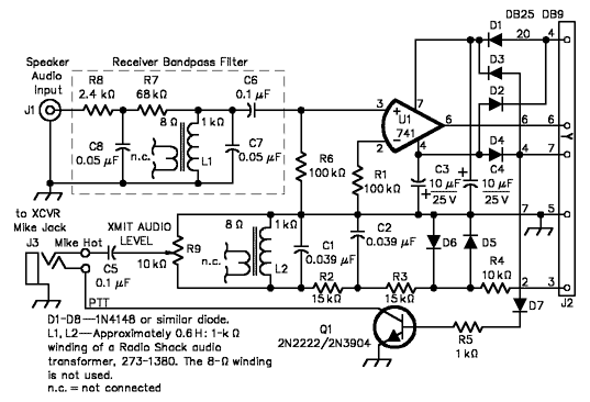
Figure 1—Schematic of an improved HamComm interface showing added components and component value changes.
There are a couple of potential pitfalls with the basic interface that can cause you to inadvertently transmit two or more sets of mark and space frequencies. I publish a Web page called K7SZL’s Unofficial HamComm Home Page that presents ways to avoid this problem, as well as other information that will help you get the most out of the program. It also offers a copy of HamComm V3.1 for download. The URL is http//www.accessone.com/~tmayhan.
Stop by and take a look. Feel free to send e-mail to me describing your experiences with HamComm or any suggestions you might have. If the volume doesn’t become unmanageable, I’ll try to respond to questions related to getting HamComm up and running.
Author Donald Cox, AA3EK, replies
I agree that the simple interface does not fully exploit the capabilities of the program. The interface shown in my article was selected from several in the HamComm documentation given the focus on inexpensive and simple ways beginners could try out digital and image modes.
QST, April 1997, page 69